
Our Work
Cage Designs
Design 1: Hardware Cloth

Early design consisting only of bent hardware cloth.

Plastic end caps added.

Cages produced to house shipment of 4,000 oysters.
Our first cage was constructed of hardware cloth rolled into a cylinder with 3D printed plastic end caps on its ends. The hardware cloth was coated with a spray on enamel in order to keep it from rusting. The plastic end caps included a door to allow access to the oysters. This design was easily transported, cheap, and quick to make. However, we found a few major problems after running some tests. The hardware cloth was also easily dented and bent out of shape, and would even rust despite the enamel. We also found that crabs were able to get through the plastic end caps in order to access the oysters inside. After giving a few prototypes to the Waterkeeper, they were able to create a solution by putting these cages into their own existing commercial cages.
Design 2: Suspension Model

Early sketch of suspension model.

Concrete weights and silicone mold.

Completed suspension model prototype.
Work on a suspension cage as a way for oysters to get full water flow without the concern of mud or bottom-feeding predators. The model consists of a buoy above water with a rope running to a concrete weight sitting on the bed of the canal. Along the rope are four mesh bags with 50 oysters each divided into sub-compartments of 10 to minimize loss. A concrete weight engineered to encourage growth of marine life was designed using CAD, a 3D printed model, and a silicone mold for concrete to be poured over. The suspension model has been tested in the Ala Wai Canal, and we plan on conducting more tests to improve the design.
Design 3: Modular Jars

David holding a stack of jars on shipment day.

Jars with connectors and lid featuring logos.

David holding jars with metal rod through them.

Box of jar connectors.
Our newest and most successful prototype is our modular system. Each module is roughly 3”x4”x4”. The top of each module has male threading while the bottom has female threading. This allows the tops and the bottoms to be screwed together. With this design we can include as many or as few of these modules as we need. This modular design allows for multiple ways for these to be deployed. We have modified the cages into “cups” with twist-on connectors. The modularity of the design allows the Waterkeeper to customize their enclosures to fulfill their oyster housing needs.
Urethane Mold

CAD model of mold intended to produce a plastic connector for the modular jars.

David removing a plastic end cap used for a hardware cloth cage from its urethane mold.
The idea for the urethane molds is to provide something that the Waterkeeper can use to produce any of our cage designs without the need for a 3D printer. The mold themselves are 3D printed, and to produce the product, a liquid urethane is injected into them. The mold is then placed into a pressure chamber to get rid of bubbles where it sets for the next 24 hours. Mold tests have been promising so far, as we have produced several end caps for the hardware cloth pieces.
Sensor Designs
The Sensors


Iteration 1: ESP32 and the Sensors
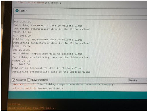
Sensor code publishing data to Ubidots Cloud.
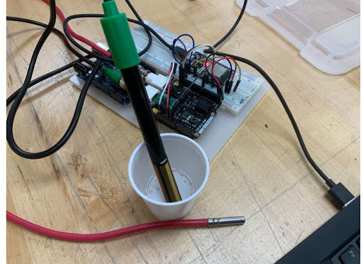
First iteration of ESP32 and sensors undergoing calibration.
The first iteration involved using an ESP32 microcontroller to control and connect the sensors to the cloud. The sensors were connected to a tentacle shield which was connected to the ESP32. The sensors take the data, then send it to the ESP32. With the controller’s wifi capabilities, the data is sent to the Ubidots data sheet. This iteration successfully connected the sensors to the data sheet in an affordable and reliable manner.
Iteration 2: Heltec LoRa ESP32 V2

Diagram of Heltec LoRa ESP32 V2 system.

Heltec board with radio wave and WiFi connection capabilities connected to a sensor.
The second iteration involves using the Heltec board, which has both radio wave (or LoRa) and WiFi connection capabilities. We made this change because the locations we want to put the sensors won’t have secure connection to wifi. Therefore, we want the sensors to send the data to a receiver, which will ultimately send the data to a data sheet. We decided to use this board because it has both of the radio wave and WiFi capabilities combined, eliminating communication issues had we instead used two boards. Again, this iteration adheres to our affordability goals. Communication between the transmitter, receiver, and Ubidots website is successful. Once the sensor reads the data, the information is sent to the Ubidots and can be read.